I love the system monitor display! I was thinking about how to add a voltage and amp meter to display on an OLED screen on my Amiga.
Any chance of the following features:
* Graphing of the the sensor values - maybe just a sparkline? Then you can visualise any fluctuations, especially for voltage.
* Sensor for 12V. I know the Gotek does not do anything with the 12V pin - but can this also be hooked up to in input pin. Or is there no more input pins available? Or may be hook up the 12V pin instead?
System monitor display.
Re: Firmware updates for the STM32/Gotek HxC floppy emulators !
this is possible. Tons of features are now possible
You can move the voltage divider on the 12V line. No change required on the resistors values.
Now if you want to monitor the +5V and +12V in the same time, this is for sure technically possible, but you will be to be good with a solder iron since there is no more free ADC input easily accessible. You can get some from ADC pins on the port A, but there are not connected/used on the Gotek pcb.
Re: Firmware updates for the STM32/Gotek HxC floppy emulators !
Sorry, excuse my ignorance - what do you mean by 'ADC input' and 'Port A'?Jeff wrote: ↑Wed Jun 12, 2019 11:08 amNow if you want to monitor the +5V and +12V in the same time, this is for sure technically possible, but you will be to be good with a solder iron since there is no more free ADC input easily accessible. You can get some from ADC pins on the port A, but there are not connected/used on the Gotek pcb.
Which of the pins in the schematic below are you referring to?:
Re: Firmware updates for the STM32/Gotek HxC floppy emulators !
The GPIOs supporting analog mode are : PA0, PA1, PA2, PA3, PA4, PA5, PA6, PA7, PB0, PB1, PC0, PC1, PC2, PC3, PC4, PC5.solarmon wrote: ↑Wed Jun 12, 2019 11:23 amSorry, excuse my ignorance - what do you mean by 'ADC input' and 'Port A'?Jeff wrote: ↑Wed Jun 12, 2019 11:08 amNow if you want to monitor the +5V and +12V in the same time, this is for sure technically possible, but you will be to be good with a solder iron since there is no more free ADC input easily accessible. You can get some from ADC pins on the port A, but there are not connected/used on the Gotek pcb.
Which of the pins in the schematic below are you referring to?:

Re: System monitor display.
OK, thanks for the details.
For now, I'll probably just use a switch to go between the 5v and 12v lines.
If there was such a STM32F105 breakout board, do you think HxC could be installed on it? If it would work I would try this just for the system monitor features alone!
Or maybe sacrifice (as an option) a feature for another analog port - for example, the buzzer pins (assuming this is an analogue port)?
Re: System monitor display.
Sure the firmware should run on this.solarmon wrote: ↑Wed Jun 12, 2019 11:56 pmOK, thanks for the details.
For now, I'll probably just use a switch to go between the 5v and 12v lines.
If there was such a STM32F105 breakout board, do you think HxC could be installed on it? If it would work I would try this just for the system monitor features alone!
yes i can add this option on the custom firmware page.
Re: System monitor display.
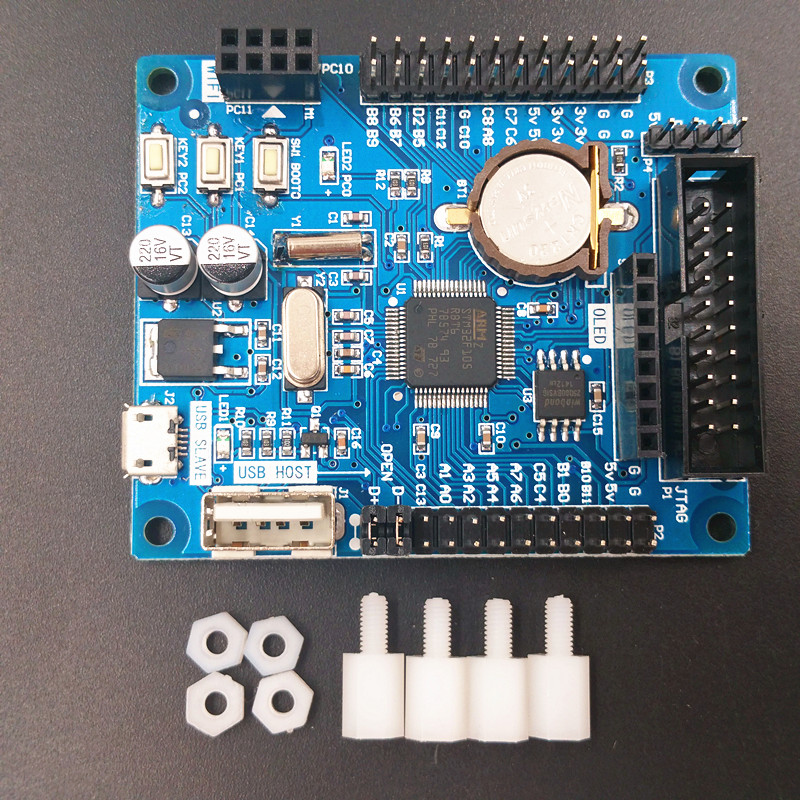
Out of curiosity, would a board like this be able to run HxC on it? It uses the same STM32F105 chip. But the pin allocations are probably totally different?
https://www.chinahao.com/product/557747844869/
https://www.chinahao.com/product/557747844869/
Re: System monitor display.
The firmware should start on this. But if you can to connect it to the floppy interface, you may need some additional buffers.solarmon wrote: ↑Thu Jun 13, 2019 11:57 amOut of curiosity, would a board like this be able to run HxC on it? It uses the same STM32F105 chip. But the pin allocations are probably totally different?
https://www.chinahao.com/product/557747844869/
Re: System monitor display.
I was thinking about using it just for the System Monitor feature, so no need for the floppy interface.
But there are probably better/cheaper options to add in a dual voltage voltmeter - I just would like to have it display ed in an OLED screen.
Looking at the available analogue pins on the Gotek STM32 chip, probably the easiest one to hook on to is PC1 (pin 9) or PC2 (pin 10).
I just need to try the feature out first, but need to get the resistors for the voltage divider circuit.
Re: System monitor display.
Hi,
Just got some 1% resistors to be able to try this feature out, so I made up the following cable to connect to the relevant pins (5V and VSS pins next to J4 and RST pins respectively)


I've used a USB Power bank to power the Gotek for the test:

I couple of points:
1. It would be good if the voltage reading displayed to two decimal places.
2. Is the voltage value rounded up or down?
3. The voltage reading seemed to be about 0.1V lower compared to the reading on my multimeter. I'm not saying that this is right or wrong, just an observation.
I'll test it when connected to a real Amiga power supply. I also need to make up another cable so that I can connect to the 12V pin instead, and longer term, have a switch to go between 5V and 12V.
Just got some 1% resistors to be able to try this feature out, so I made up the following cable to connect to the relevant pins (5V and VSS pins next to J4 and RST pins respectively)
I've used a USB Power bank to power the Gotek for the test:
I couple of points:
1. It would be good if the voltage reading displayed to two decimal places.
2. Is the voltage value rounded up or down?
3. The voltage reading seemed to be about 0.1V lower compared to the reading on my multimeter. I'm not saying that this is right or wrong, just an observation.
I'll test it when connected to a real Amiga power supply. I also need to make up another cable so that I can connect to the 12V pin instead, and longer term, have a switch to go between 5V and 12V.
Re: System monitor display.
I did this a while back, but forgot to post about it.
I tested a setup that allowed me to switch between the 5V and 12V lines:

I needed to connect to the 12V line, which didn't have a pin header - so I soldered a right-angle header pin to the 12V pin, from the underside of the Gotek board:


And added a temporary switch between the resistors and the JC pin. Not pretty, or practical, but it is just for testing!:

System Monitor is now able to display the 12V voltage when I switch to it. Although, it still seems to be off compared to my multimeter - which shows 11.69V:

I tested a setup that allowed me to switch between the 5V and 12V lines:
I needed to connect to the 12V line, which didn't have a pin header - so I soldered a right-angle header pin to the 12V pin, from the underside of the Gotek board:
And added a temporary switch between the resistors and the JC pin. Not pretty, or practical, but it is just for testing!:
System Monitor is now able to display the 12V voltage when I switch to it. Although, it still seems to be off compared to my multimeter - which shows 11.69V: