Who has relocated the buttons and LCD for custom casing? I am looking for a way to install my HxC into my Amiga 1200.
Please post your photos/videos of your installation (no matter which hardware platform) here.
Example: Blakespot's HxC 2001 Amiga 2000 install
Relocating the buttons and LCD
Re: Relocating the buttons and LCD
This is a prime example: http://metaneutrons.blogspot.com/2011/0 ... mment-form
My blog:8-bit living… and dreaming away…
Re: Relocating the buttons and LCD
Howdy.
I recently finished the installing hxc sd card adapter into my ensoniq eps.
I wanted to move the lcd in place of the disk drive so I had to connect it via ribbon cable, and then relocate the buttons as well.
A standard ribbon cable fits pretty well onto the old lcd pins on the hxc, though the connector is actually a little too big, so it doesn't sit centered on the pins.
When soldering the ribbon cable onto the lcd, you have to figure out which wire corresponds to the first pin of the lcd header, then solder every-other wire, as the wires in the ribbon map to left-to-right and top-to-bottom on the connector. You also want to take notice and omit 9 wires in the middle, as the lcd header is split in two groups of pins, and the middle 4 pins on the lcd are unused.
The buttons are easy enough to move, as you just solder extension wires to the bottom of the hxc where the buttons are already soldered. I did not remove my old buttons (though I did cut them down to fit into a casing).
I had to cut a pass through in the back panel of the disk-holder of the eps - that plastic is really thick and this was hard to do. The picture is taken in the middle of the process, before I removed that last piece and sanded it all down.
Here's everything sitting in the chassis of the eps, without casing.
The casing ended up being an empty cassette case - the HxC fits PERFECTLY into a tape case if you remove the inner tabs, and fold /trim down the drive selection jumper and the on-board buttons. I also cut out the plastic where the cables plug in, and on the front where the sd card would go. I placed it in the case with the bottom part of the HxC against the flat part - the front- of the tape case.
A black paint job, and a little faceplate to put the lcd in where the disk drive used to go...(probably could build this into a floppy drive) - here's the first incarnation...
Here's another shot of the finished mod - an unexpected plus is that the leds sort of emanate from underneath the external casing now, so it's a bit more subtle.
The original paint job on top of the tape case wasn't perfect, so I found a nice, zen picture off an old book to cover it up.
Here you can see the velcro I used to secure the new housing to the sampler, and you can also see the ribbon cable for the lcd, and the bent drive selection jumper.
Doing it this way gave me a little less cable to work with, as I had to flip everything over...ribbon cable is not the most forgiving thing in the world.
Another member here did a really great EPS install where he moved the lcd and buttons as well...you can read about his mod, and also see a great video in this thread: viewtopic.php?f=17&t=305&start=45
-J
Re: Relocating the buttons and LCD
hi,
i cant seem to find a definate answer...and i dont have a HxC yet.
How do you remove the LCD screen? just pull it off, remove some screws or desolder?
i cant seem to find a definate answer...and i dont have a HxC yet.
How do you remove the LCD screen? just pull it off, remove some screws or desolder?
Re: Relocating the buttons and LCD
Just pull it off.blip wrote:hi,
i cant seem to find a definate answer...and i dont have a HxC yet.
How do you remove the LCD screen? just pull it off, remove some screws or desolder?
Re: Relocating the buttons and LCD
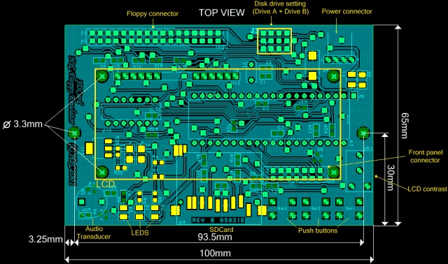
You actually don´t need to take off the buttons, neither have to solder external buttons to where the original buttons are/were.
You can connect controllbuttons to J2 of the HxC . Pin 1, 7,8,9
Check the HxC manual and schematics.
you can find a picture here with pins on J2 for external buttons.
http://torlus.com/floppy/forum/viewtopic.php?f=14&t=714
Last edited by 12bitski on Tue Nov 01, 2011 1:01 am, edited 1 time in total.
Re: Relocating the buttons and LCD
You can also use pins on the side of the ribbon cable, where you connect the display. You just need a row of these pins, you normaly solder on a board. If the pins are a little too long, you can simply cut them .jeffe wrote: I wanted to move the lcd in place of the disk drive so I had to connect it via ribbon cable, and then relocate the buttons as well.
A standard ribbon cable fits pretty well onto the old lcd pins on the hxc, though the connector is actually a little too big, so it doesn't sit centered on the pins.
When soldering the ribbon cable onto the lcd, you have to figure out which wire corresponds to the first pin of the lcd header, then solder every-other wire, as the wires in the ribbon map to left-to-right and top-to-bottom on the connector. You also want to take notice and omit 9 wires in the middle, as the lcd header is split in two groups of pins, and the middle 4 pins on the lcd are unused.
-J
So there´s no need to solder. You just need to check to connect the plug the same way, that it is on the HxC.
just a little example of the pins
Re: Relocating the buttons and LCD
Thanks for the pictures... relocating the LCD will work out, i am sure...
I now have some questions on the frontpanel connector
- Can someone please explain per pin what can be connected?
- Which pin i need to use as GND for BUTTON_UP(7), BUTTON_SELECT(8) and BUTTON_UP(8)?
I will post a complete installation description on my blog, listed under: HxC2001 SD card implemention, using the Metaneutrons method
My blog:8-bit living… and dreaming away…
-
- Posts: 132
- Joined: Sun Mar 20, 2011 6:55 pm
Re: Relocating the buttons and LCD
VSS is the ground.
I guess you understand what the button pins do.
All the other go to the LCD which has a standard interface:
http://en.wikipedia.org/wiki/HD44780_Character_LCD
I guess you understand what the button pins do.
All the other go to the LCD which has a standard interface:
http://en.wikipedia.org/wiki/HD44780_Character_LCD